
MRacing - ADM

ADM revision #2
I designed the Autonomous Distribution Module, it distributes power and signals across all of the Autonomous System components.
It has 4 CAN to USB converters, 6 electronically controlled fuses, shutdown circuit logic and relays, status LED logic, monitoring for EBS relays, and pressure sensor ADCs,

ADM revision #1 (top)
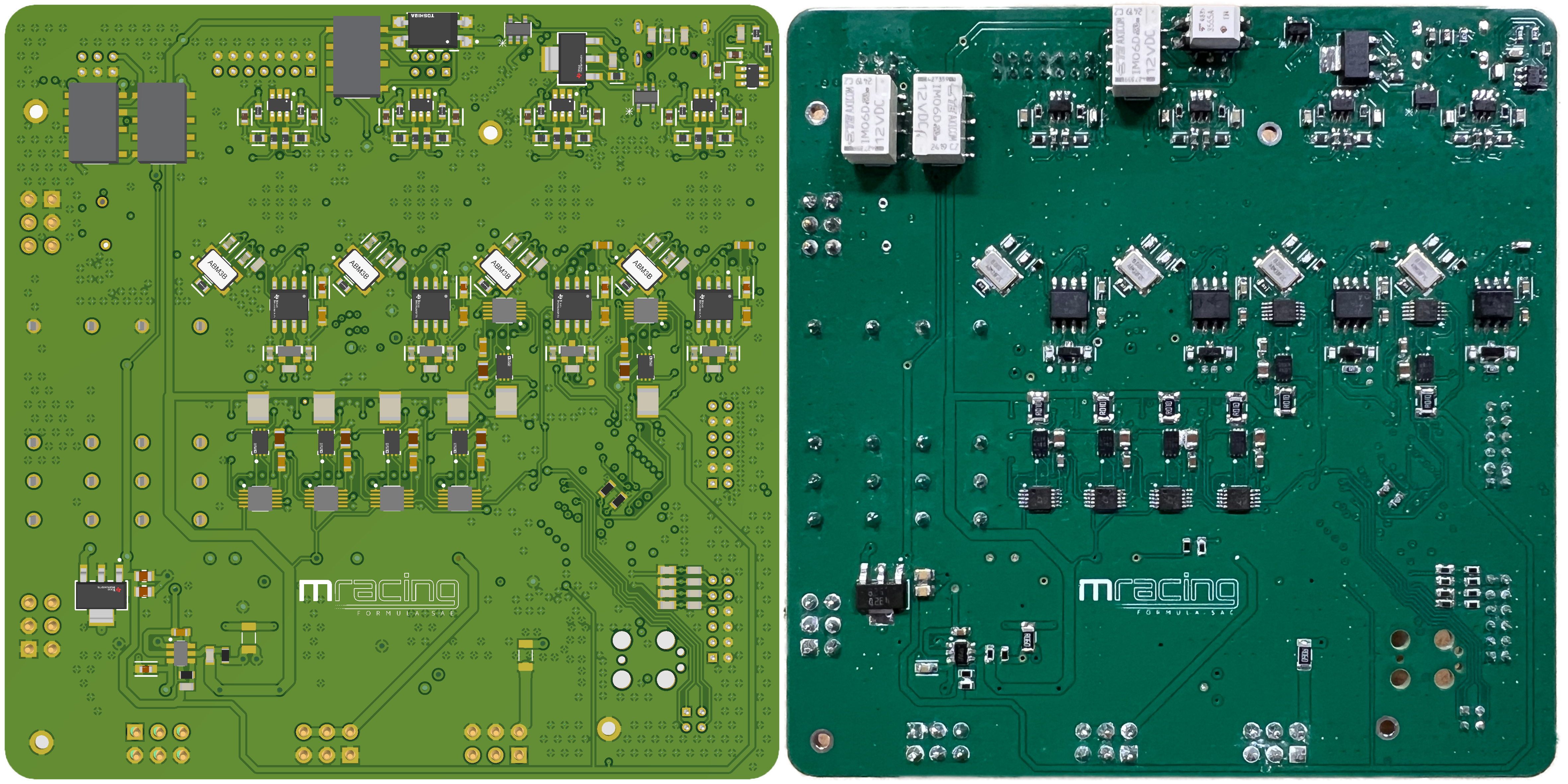
ADM revision #1 (bottom)

Design for the ADM started as a block diagram to layout all of the requirements and IO
The ADM handles many of the FSG rules, one example is the buzzer rule.
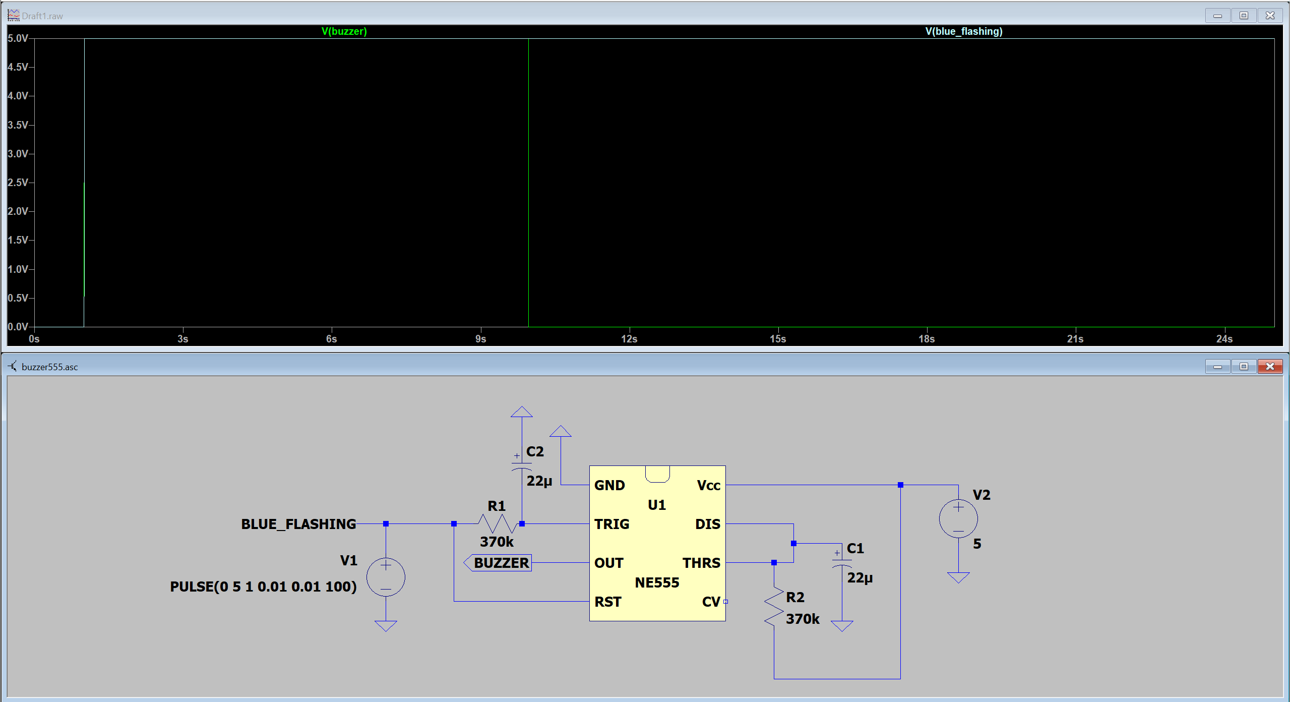
By rules, a buzzer needs to sound at an frequency of 1Hz to 5Hz with 50% duty cycle with a total duration between 8s and 10s after entering the "AS Emergency" state.
This LTspice simulation of a monostable 555 circuit with rising-edge triggering meets the 8-10s requirement. When Vin receives a step input (at 1s here), Vout remains HIGH for about 9s, then goes LOW. This design reduces failures from flashing faulty STM code, allowing control of both the status lights and buzzer with just four on/off digital signals from the STM.

After designing the ASSI, I made a logic table before finalizing the schematic to be extra sure that the four control signals actually
do what I want them to do.

Using the STM IDE, I made sure that all of the signals are assigned to pins which actually support the signal type.
Contact
- terrytao19@gmail.com
- 631-951-7354
- 2603 Draper Dr, Ann Arbor MI 48109