
MRacing - EBS
I designed the Emergency Braking System, it actuates the brakes at the end of an autonomous mission, or whenever there is a fault
or in the worst case when the remote emergency stop button is pressed.
Design for the EBS started as a block diagram of how and when the system will need to trigger. Using this and the rules,
I developed requirements to determine the data needed from the car to specify pressures and hardware for the EBS.

From driving data, I found the lower bound brake pressure for both the rears and the fronts for 10[m/s2] as specified by rules.
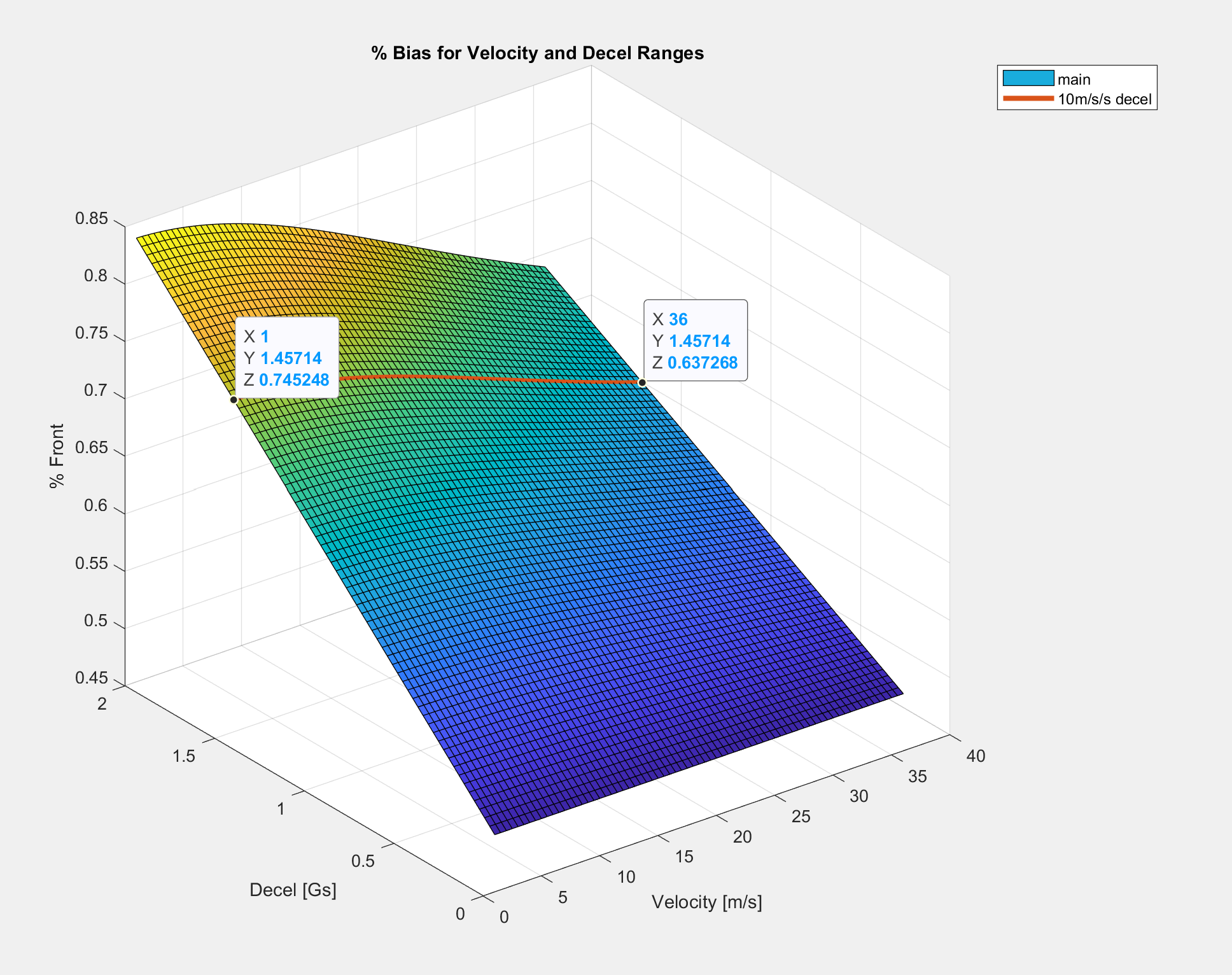
To spec the pressure regulators, I needed to know what the optimal front/rear brake bias is.
Because of number of pistons in front vs rear calipers, there is a 66% front torque bias when both lines have equal pressure.
66% is within the range for optimal bias at the velocities we are operating in.
Therefore we can safely use the same spec pneumatic pressure regulator on each of the rear/front lines

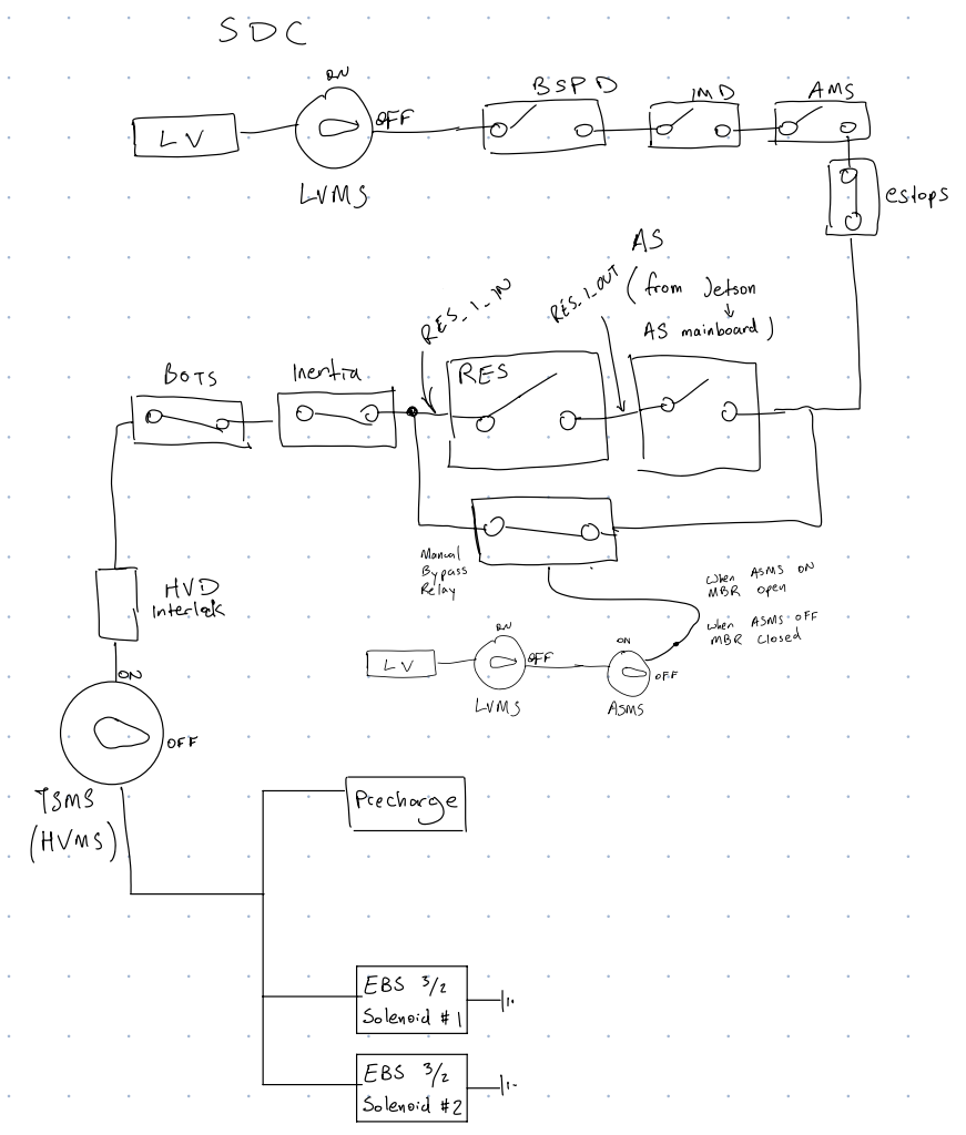
Once I got the pressure specs, I drew a block diagram for the first revision of EBS
Using the block diagram, I created the rev1 EBS design with two linear pneumatic actuators directly pushing the brake pedal.
Issues with this design are discussed below.
Issues with this design are discussed below.

EBS rev2 diagram, the improvements include:
Series wiring eliminates the need for a block manifold
3/2 manual release valve keeps high pressure in when open
Keeps access hole open
Series wiring eliminates the need for a block manifold
3/2 manual release valve keeps high pressure in when open
Keeps access hole open

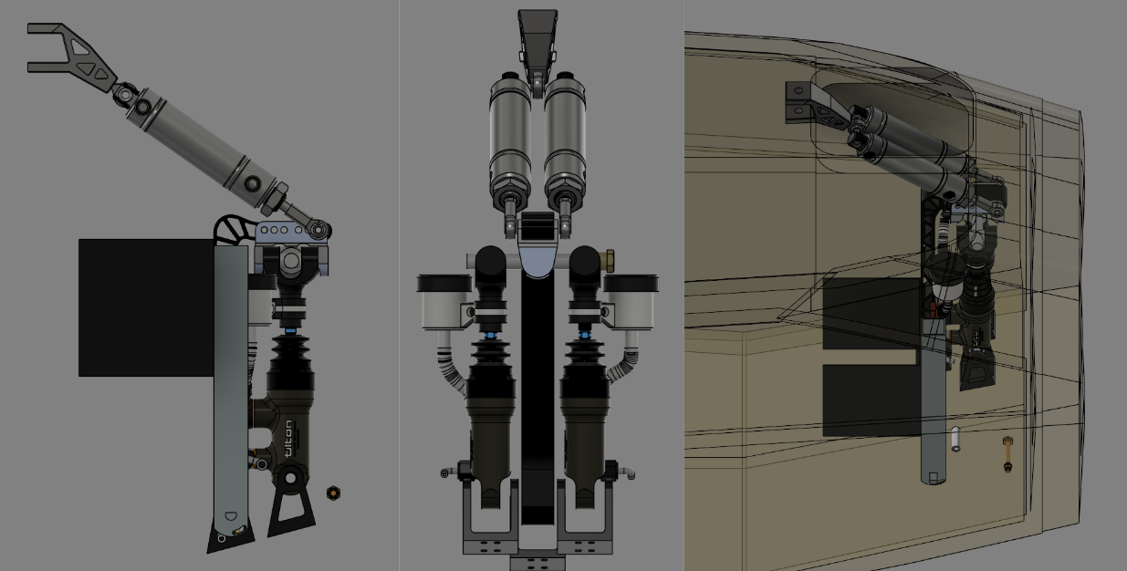
EBS rev2 actuator design

EBS rev2 actuator design
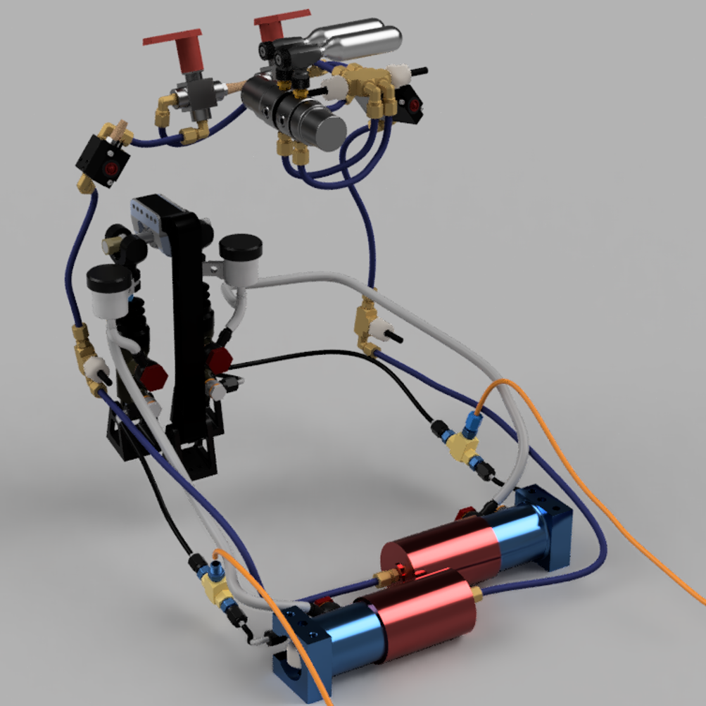
EBS rev2 in its entirety
Contact
- terrytao19@gmail.com
- 631-951-7354
- 2603 Draper Dr, Ann Arbor MI 48109